USBGPS OpenSource Project homepage  

¡¡

Project Maintainer: Yu Lu   


Introduction

Hardware

Firmware

Device Driver

App Software

Download

Document

Thanks


User Application

This part is the highest level code of the whole project. Firmware, hardware and device driver together provide a interface to control GP2021 in real time. But they know nothing about GPS. The application code implements all GPS processing through this interface. Theoritical speaking, this part should be able to run on different hardware interface only with minor change. For a beginner to understand this part, some basic theory about GPS is necessary.

Basic GPS Theory
As we know, a GPS receiver can provide estimation about user's position, velocity, time( namely, P.V.T. estimation). Here I just make position estimation as an example. In ECEF frame, there are three unknown about position, x,y,z. To solve these 3 unknowns, we need at least 3 equations:

S1 = [(x1-x)2 + (y1-y)2 + (z1-z)2]1/2
S2 = [(x2-x)2 + (y2-y)2 + (z2-z)2]1/2
S3 = [(x3-x)2 + (y3-y)2 + (z3-z)2]1/2
Here (xi,yi,zi) is the position of satellite i. Si is the range from satellite i to user.

Satellite's position can be calculated accurately from ephemeris data. But how can we know the range? It's easy to think about the method of using travel time to get range: multiplying the travel time with speed of light. But how to know the accurate travel time? Someone would say: if we know the tranmitting time and the arrival time, then we can know the accurate travel time. Good idea! But how can we know transmitting time and arrival time? It seems that we are introducing more unkowns.

Don't be frustrated! It seems that we have more unknowns than before, that is not true. At least we can know the transmitting time as long as we have locked that satellite's signal. Let me show that:
Till now, we have solved the transmitting time. How about the arrival time? No way. Someone would think that we can read local time from receiver's RTC. That's impossible because receiver's clock has large drift and bias( except that every receiver is equipped with one atomic clock). As mentioned above, even 1ms bias in time will give out 300KM bias in range. So we can't tell the accurate arrival time for each satellite. Thus we still have too many unknowns to solve.

But correlator( here, GP2021 ) can latch measurement data (CODE_SLEW,CODE_PHASE, CARRIER_CYCLE_LOW, CARRIER_DCO_PHASE,EPOCH,CODE_DCO_PHASE,CARRIER_CYCLE_HIGH,EPOCH_CHECK) of all 12 channels at the same instant. That is great, because it means that all satellites' signal share the same arrival time. Now for the unknowns, we only introduce one more unknowns: receiver's clock bias tb. For 4 unknows, (x,y,z,tb), we need 4 equations as below:

S1' = [(x1-x)2 + (y1-y)2 + (z1-z)2]1/2 - Ctb
S2' = [(x2-x)2 + (y2-y)2 + (z2-z)2]1/2 - Ctb
S3' = [(x3-x)2 + (y3-y)2 + (z3-z)2]1/2 - Ctb
S4' = [(x4-x)2 + (y4-y)2 + (z4-z)2]1/2 - Ctb
Here (xi,yi,zi) is the position of satellite i. Si' is the pseudorange from satellite i to user, C is the speed of light, tb is the clock bias.

The above nonlinear equations can be solve in recursive way. That is a mathematic question, please refer to textbook for more details. Now we know that 4 locked satellite are enough for positioning. In my hardware there are 6 channels available, so there is no problem to solve user's location. But DOPs(GDOP,VDOP,HDOP,TDOP,...) will be compromised due to this limit.

From above analysis, it can be seen that tracking loop is very important in a GPS receiver. The performance of tracking loop affects greatly the performance of receiver. I still make above equations as example: We need the information of satellite accurate position, which is calculated using ephemeris data; but the latest ephemeris data is available only after tracking loop lock satellite signal and recover navigation message. To calculate the pseudorange, we need know the accurate transimitting time of each satellite signals; This is possible only when tracking loop is locking the signal. So in a GPS receiver, its most important duty is signal acquisition and signal tracking.

GPS signal is typical CDMA signal. It is a kind of spreading-spectrum signal. After travelling from satellite to the earth, GPS signal is "buried" in thermonal noise. It can be detected and decoded because of the strong auto-correlation property of PN code(C/A code). This means there will be two loops in GPS receiver: code loop and carrier loop. Code loop is used to de-spread PN code(C/A code), while carrier loop is used to de-modulate the carrier.

More information about tracking loop is beyond the scope of this webpage. For details, please have a look at these reference.

Code Description
There are 4 threads running in application code: screenthread, sampthread, navthread,gpsthread.

These threads are synchronized through EVENT and CRITICAL_SECTION. In my code, there are three global EVENT variable: newdataEvent, gpsEvent, dispEvent. Sampthread uses newdataEvent to inform Navthread that there are new data arrived; Navthread use gpsEvent to inform Gpsthread that new measurement are available for pseudorange calculation and PVT solution; DispEvent is used to tell screenThread to update display.

In my code, I defined several classes, whose duties are descripted as below:

Class
Description
IoInterface
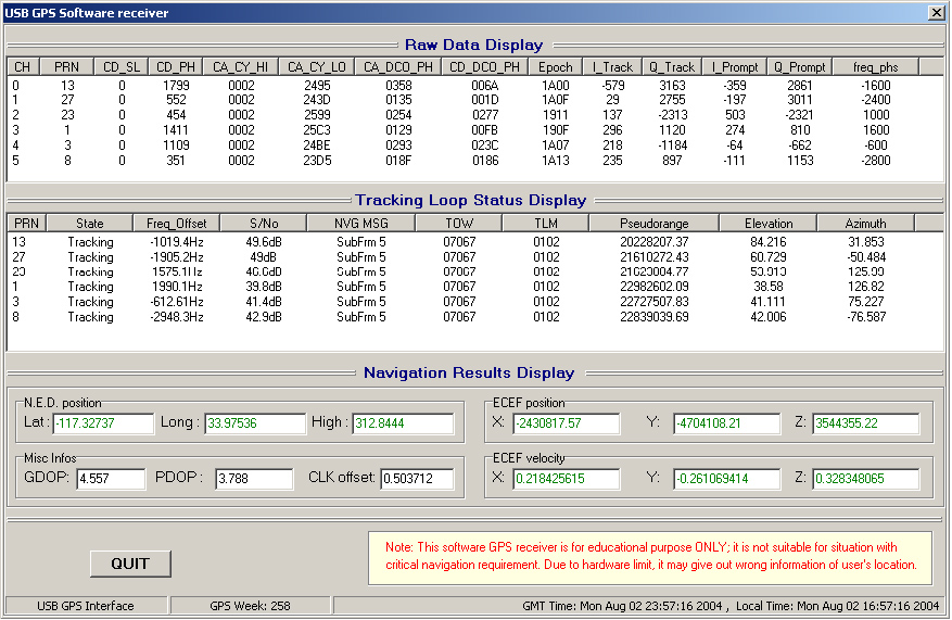
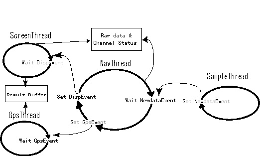
Provide functions to communicate with device driver, to control hardware, also provide functions to copy raw data from GP2021 to navthread, and to get processing result from navthread.
GPS_Nav
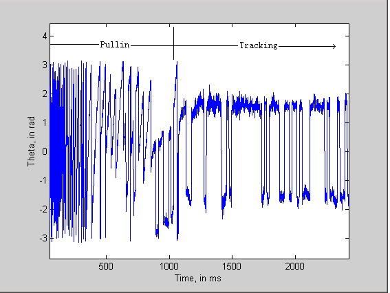
Provide funtions to implement tracking loop with 4 states: acquisition, confirm, pullin, tracking. When signal is being locked, read measurement to calculate accurate transmitting time. Also read navigation message from tracking loop.
GPS_Func
Provide gps-related functions, including Geodetic to ECEF frame transformation (and vice vesa), calculate satellite's position from Almanac data and ephemeris data, resolve estimation of PVT ,etc
TForm1
Implement display of raw data, tracking loop status for each channel, also navigation result. This class is also responsible of system initialization, global variable initialization, etc.


The timing relationship among these threads is illustrated as below:


 timing relationship among threads


About the tracking loop, the basic idea is the same with Clifford's code. The loop also contains 4 states: acquisition, confirm, pullin, tracking. Here I don't want to repeat the basic, readers are encouraged to read Clifford's detail description in this link: http://home.earthlink.net/~cwkelley//receiver_operation.htm. I just want to mention some special considerations for the special feature of USB hardware, which are the most tricky parts in the whole project.

From the descriptions of hardware and firmware, it can be seen that every time application get one frame data from GP2021, that frame will contains 6 channels' accumulation reault in about 3.6ms. In 3.6ms, each channel will have 3 or 4 accumulations happened. So each time, tracking loop code will control GP2021 based on these 3 or 4 accumulcations instead of just 1 accumulation. That arises one question: how to determine the correct control setting from 3 or 4 accumulcations? For each accumulation, I can get 4 raw data: TRACK_Q, TRACK_I, PROMPT_Q, PROMPT_I. From these raw data, 4 new variables can be got:

     TRACK_MAG = (TRACK_Q2+TRACK_I2)1/2
     PROMPT_MAG = (PROMPT_Q2+PROMPT_I2)1/2
     THETA = ATAN2(PROMPT_Q, PROMPT_I)
     CODE_PH = (TRACK_MAG - PROMPT_MAG)/(TRACK_MAG + PROMPT_MAG)

TRACK_MAG and PROMPT_MAG are used to accquire signal in accquisition state. THETA is used to control carrier loop , while CODE_PH is used to control code loop.

So for each frame, there will be 4(or 3) TRACK_MAG , 4(or 3) PROMPT_MAG, 4(or 3) THETA and 4(or 3) CODE_PH for each channel. In next analysis I will assume that there are 4 accumulation results in one frame for convenience.

Because 4 accumulation results of the same frame share the same carrier loop phase and the same code loop phase, it is easy to think about using the mean of TRACK_MAG and PROMPT_MAG, namely:

     MEAN_TRACK_MAG = (TRACK_MAG1+TRACK_MAG2+TRACK_MAG3+TRACK_MAG4)/4
     MEAN_PROMPT_MAG = (PROMPT_MAG1+PROMPT_MAG2+PROMPT_MAG3+PROMPT_MAG4)/4
Thus new CODE_PH can be calculate using the mean of MAGs:

     CODE_PH = (MEAN_TRACK_MAG - MEAN_PROMPT_MAG)/(MEAN_TRACK_MAG + MEAN_PROMPT_MAG)
Till now, it's OK, but what about THETA, can I still use the mean of 4 THETAs? The answer is no, because in 1ms THETA could change a lot, especially in PULLIN state. To make full use of all 4 accumulation data, I need to calculate the total change of THETA. Because ATAN2(x,y) gives a value in the range of [-PI, +PI], there will be PI-jump in THETA, eith from +PI to -PI or from -PI to +PI. The following graph shows this:


 PI-phase jump


The left graph show the 4 THETA when the phase of feedback lead reference, it can be seen that +PI to -PI jump happens between THETA2 to THETA3; The left graph show the 4 THETA when the phase of feedback lag reference, it can be seen that -PI to +PI jump happens between THETA1 to THETA2. In my code, I implement this PI-compensation as below ( from GpaNav.cpp ):


     ...
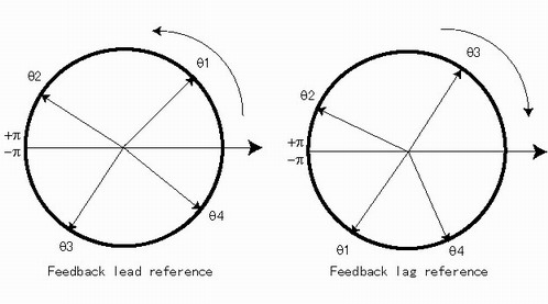
     ca_t = ch[idx].theta[l] - ch[idx].theta[l-1];
    
     if( fabs(ca_t) > PI )
      ca_theta = ca_t > 0? ca_t - 2*PI : ca_t + 2*PI;
     else
      ca_theta = ca_t;
     ch[idx].total_theta += ca_theta;
     ...
After this PI-compensation,ch[idx].total_theta stores the correct phase change for these 4 accumulation data, it can be used to control FLL of carrier loop.

Another important trick is in the TRACKING state: when TIC happens, application code need to calculate the accurate transimitting time of satellite signal. Generally this is done through reading the value of EPOCH register, which can give the 20ms and 1ms portions(CHx_1MS_EPOCH and CHx_20MS_EPOCH). But the value of EPOCH register is correct only when it's reset at the data bit transit instant( at the edge of 20ms). In ISA hardware, it's easy to do that; while in USB hardware, it's impossible to do that cause USB communication is not burst-accessable. The way I calculate the transmission time of different satellite signal is to count one ms by one ms in my code. So this will introduce 1 or 2ms ambiguity. To solve this ambiguity needs firmware's help.

GP2021 provides one read-only register EPOCH_CHECK for each chanel, reading this reg gives the instantaneous value of the CHx_1MS_EPOCH and the CHx_20MS_EPOCH. In Zarlink's document, the purpose of EPOCH_CHECK is to verify if the EPOCH counter have been properly initialized by software. In USBGPS project, I use this register for my special purpose. In my firmware, firmware send 6-channels EPOCH_CHECK if TIC doesn't happen. Then at the data bit transit instant, application code can know the value of CHx_1MS_EPOCH although it can't reset it. This value can be a reference for the EPOCH counter when TIC happens. This value is used to solve the above mentioned 1ms ambiguity. The code segment implementing this is as below( from GpaNav.cpp ):


     ...
    
     int ms_diff, tic_ms_mod20, compensate_ms;
    
     ms_diff = (frm_4ms_6ch.ch_cntl[idx].epoch) & 0xff;
     ms_diff -= ch[idx].epoch_ref; // minus epoch_check value
     if(ms_diff < 0) ms_diff += 20;// get the value of [0 -- 19]
     tic_ms_mod20 = ch[idx].TIC_mscount %20;
     if( fabs( ms_diff - tic_ms_mod20) < 10)
      compensate_ms = ms_diff - tic_ms_mod20;
     else // ms_diff and tic_ms_mod20 should be very close,
      {
      if( ms_diff > tic_ms_mod20)
        compensate_ms = -(tic_ms_mod20 - ms_diff + 20);
      else
       compensate_ms = (ms_diff - tic_ms_mod20 + 20);
      }
    
    
     ch[idx].tr_time = ch[idx].tr_time_HOW+(ch[idx].TIC_mscount+compensate_ms)*0.001+
     (frm_4ms_6ch.ch_cntl[idx].code_phase)/2.046e6 +
     (frm_4ms_6ch.ch_cntl[idx].cd_dco_phase)/2.046e6L/1024.;
    
     ...
Here ch[idx].epoch_ref stores the value of EPOCH_CHECK for that channel, ms_diff stores the value of ch[idx].epoch - ch[idx].epoch_ref . And compensate_ms is the value that should be added to ch[idx].TIC_mscount in order to solve 1ms ambiguity. The value of compensate_ms is small, such as -2,1,or 0. In most time, this method will give correct transmitting time; but sometimes( although seldomly ), it will fail. If someone can find better and more stable method to solve this problem, welcome to tell me.

Performance
This is GUI interface of application :
 screenshot of application


This is paragraph of carrier-loop's freq during Pullin & Tracking states:
 carrier loop doppler frequency


This is more closer lookup of carrier-loop carrier freq :
 finner carrier loop doppler frequency


This is the data bit output during Pullin and Tracking states:
 data bit output


This is the carrier-loop's phase(THETA) during Pullin & Tracking states:
 carrier loop phase


Useful Reference


Welcome to USBGPS Opensource Project Homepage
© Copyright 2004    Email:   Yu Lu