USBGPS OpenSource Project homepage  

กก

Project Maintainer: Yu Lu   


Introduction

Hardware

Firmware

Device Driver

App Software

Download

Document

Thanks


Firmware

Firmware plays a very important role in the whole system. Its duty is not complicated, only includes the following: Here I say 6 channels because: Due to the limit of on-chip RAM of DS89C420 and USB1.1 bandwidth, I have no way but to decrease the processing channel from 12 to 6 in order to process them in real-time. As the project is for educational purpose, 6 channels are still enough to finish all GPS functions. (Actually 4 channels are already enough if we don't care much about GDOP.)

Here I don't want to say more about the implementation of USB protocal, because it has nothing to do with GPS. USB communication is only the mothod, it is not my goal. For any interested person for this, please read USB1.1 specification and datasheet of USBN9603. These two documents are very important if you want to understand the USB part of my firmware. (If you want to understand USB protocal such that you can design your USB device, you must be well-prepared. USB is not simple as RS232 although they are all "serial" communication.)

Although firmware's duty is not complicated, it doesn't mean that it's easy to achieve . I must say, firmware cost me almost 50% of all the time and energy which I spent on this project. To finish the job is a matter, to finish the job in real time is another matter. Most of my time and energy was spent on optimizing the firmware such that the firmware can finish all jobs in real time.

In order to understand my firmware, one should has some basic knowledge of USB protocal. USB is not a burst-access bus. ISA or PCI is burst-access bus, which means that you can inquire a read/write command at "any" time and get the result of that command "at once". Here I use "any" and "at once" because strictly speaking it is still delayed by one or two instructions, which is at microsecond ( or even nanosecond ) level, so you can still regard that access as "any" time and "at once". USB communication is based on data packet, and all transaction of USB is scheduled on the 1MS frame determined by system USB controller. This means that you can request a read/write command to USB device and get the result of that command after time t. But t is at the level of MS. This make me not be able to poll the status of GP2021's ACCUM_STATUS_A registers, to determine which channel has new accumulation data and then get that new data. In the case of ISA or PCI, I can do that without any problem. Actually, Clifford did in that way in his code. But for USB, I can't do that because after I get the value of ACCUM_STATUS_A, maybe 1ms has passed already. Here you should keep this in mind: Correlators of GP2021 will generate new accumulation data every 1MS. So missed data is inevitable in that way.

My solution to this dillema is to get the accumulation data of each channel no matter what is the value of ACCUM_STATUS_A, organize these data into packet and send to host software in PC throgh USB. The host software will determine which channel has valid new accumulation data by checking the value of ACCUM_STATUS_A. To make sure that there is no missed data, the interval between two consecutive collections should be less than 1MS. In my case, this interval is 0.9MS which is determined by DS89C420's timer setting. Also considerring the speed of USB communication, I have to organize 4 collections into one packet for one transaction. This is because the more data one transaction(one IRP) contains, the more efficient that USB communication is.

Based on the above analysis, the timing sequence of data collection and USB communication is as below:


 timing sequence


From this graph, we can see that one transaction( one frame, but here frame is not the USB "frame") contains 4 collection. Action 1 finish the collection for 6 channels. Also one transaction contains receiving command from PC. Action 2 finish the job of sending these commands to GP2021. We can also see that double buffers are used both at microcontroller side and at PC side. While one buffer is used for processing, another buffer is used for communication. So communication and processing is pipelined to achieve minimum latency between them.

To gain highest efficience, some functions in firmware are finished in assembly language. Compiler for firmware is Keil C 7.0. DS89C420 has 1KByte on-chip RAM. Based on above analysis, I need three buffers : In my firmware, the mapping of these 3 buffers in 1KByte RAM is illustrated as below:


 buffers mapping


Buffer 1 is from 0x00--0x15f, which has the following data structure:

Address Offset
Description
0x00-0x37
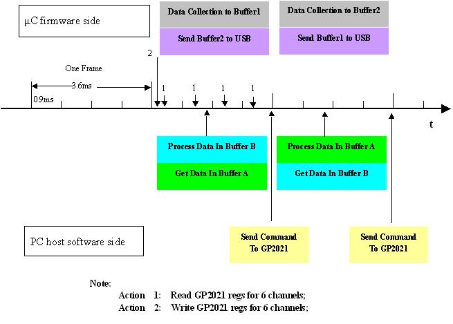
Collection 1(updated in the first 0.9MS ) :
accum_status_c,meas_status_a,accum_status_a,accum_status_b;( 8 bytes)
6 channels' accumulation data; ( 6*8 bytes)
0x38-0x6f
Collection 2(updated in the second 0.9MS ) :
accum_status_c,meas_status_a,accum_status_a,accum_status_b;( 8 bytes)
6 channels' accumulation data; ( 6*8 bytes)
0x70-0xa7
Collection 3(updated in the third 0.9MS ) :
accum_status_c,meas_status_a,accum_status_a,accum_status_b;( 8 bytes)
6 channels' accumulation data; ( 6*8 bytes)
0xa8-0xdf
Collection 4(updated in the fourth 0.9MS ) :
accum_status_c,meas_status_a,accum_status_a,accum_status_b;( 8 bytes)
6 channels' accumulation data; ( 6*8 bytes)
0xe0-0x13f
6-channels' measurement( updated only when TIC happens) :
Each channel has : CODE_SLEW,CODE_PHASE, CARRIER_CYCLE_LOW, CARRIER_DCO_PHASE, EPOCH,CODE_DCO_PHASE,CARRIER_CYCLE_HIGH,EPOCH_CHECK; ( 6*16 bytes)
0x140-0x143
Timestamps for 4 collections; ( 4 bytes)
0x144-0x15f
Debug info or reserved for future; ( 28 bytes)

Note that the space for 6-channels measurement, namely, from 0xe0 to 0x13f. This space is used to store 6-channels measurement when TIC happens. But when TIC doesn't happen, it's used to store 6-channels' EPOCH_CHECK. The purpose of this is descripted in Application Software .

Buffer 2 has the same data structure with Buffer 1 ,except that its beginning address is 0x160. So its range is from 0x160--0x2bf.

Buffer 3 is used to store PC's command, whose range is from 0x2c0--0x33d. Its data structure is defined as below:

Address Offset
Description
0x00
Flag: ( 1 bytes)
1: PC wants firmware to send collections ;
0: PC donot want firmare to send collections;
0x01
Number of commands; (1 byte)
Must be less than 41;
0x02-0x04
Command 1: (3 bytes)
  • address;
  • high byte;
  • low byte;
...
...
0x7a-0x7c
Command 41: (3 bytes)
  • address;
  • high byte;
  • low byte;

So host software can send as many as 41 commands to GP2021 each time. Let's check if 41 commands are enough to control 6 channel:
For one channel, to acquire signal and maintain loop tracking, one only need to set code phase( writing to CHx_CODE_SLEW_COUNTER), set carrier loop frequency ( writing to CHx_CARRIER_DCO_INCR_HIGH,CHx_CARRIER_DCO_INCR_LOW ), and set code loop frequency( writing to CHx_CODE_DCO_INCR_HIGH,CHx_CODE_DCO_INCR_LOW ), totally 5 commands. For 6 channels, 30 commands are enough. So 41 commands are enough for controlling 6 channels.


Welcome to USBGPS Opensource Project Homepage
© Copyright 2004    Email:   Yu Lu