USBGPS OpenSource Project homepage  

กก

Project Maintainer: Yu Lu   


Introduction

Hardware

Firmware

Device Driver

App Software

Download

Document

Thanks


Hardware

The total hardware includes hacked BAE SuperStarTM GPS receiver and USB interface board. For hacked SuperStarTM receiver, Clifford Kelly has very detailed description: http://home.earthlink.net/~cwkelley/how_to_hack_a_superstar.htm; I will only focus on the USB interface board.

When I decided to design a USB interface board, I had two considerations: For the first consideration, the project is not just for myself, it is also prepared for others. I can use TI's DSP processor to finish the USB interface board, but not everyone can own a developement tool for that DSP processor. So to choose the microprocessor, I need to consider its difficulty level of design for other one. That's why I choose 8051-family microcontroller: it's easy to learn , to design, to build up hardware board. I believe every senior student majorring in EE can write code for MCS-51 controller after several days' studying. Also there are very rich resource about MCS-51 design in internet.

For the second consideration, my idea is: PC will finish all the processing for GPS signal. In this way the developper can control all the processing in software. This is one important design goal of the project. The hardware only collect new accumulation data from GP2021, and if TIC happens, it'll collect measurement data; then it will send these data to PC, waiting for the result of PC; after the command of PC is ready, send the PC's commands to GP2021. Hardware will never argue with PC, like this : "Why do you want to send 0x3010 to GP2021's control register, I think 0x3020 is better!" That is not permitted.

Based on these two considerations, I choose Dallas DS89C420 as my controller of interface hardware. This controller has a lot of interesting features , for details please refer to its datasheet and User's Guide. I only want to mention one of them: the controller is a enhanced version of 51 controller, most of its instruction only consume one or two oscillator cycles, while traditional 51 controller will consume at least 12 oscillator cycles for each single instruction! This feature make it the fastest 51 drop-in in the world. Here I want to express my thanks to MAXIM semiconductor for their free samples of DS89C420 for this project.

Another design goal is that user should be able to download their compiled firmware to hardware without any hardware programmer, namely, ISP(In-System-Programmable). Fortunately, DS89C420 provides such ability: it has 16KB flash on chip , and a build-in ROM loader; The ROM loader can be invoked at any time by setting RST=1, EA=0, PSTN=0; After ROM loader is triggered, user can download objective code using PC-based software tool.

So in my hardware design, there are mainly three parts: interface with USBN9603, interface with GP2021 and interface with serial port.

DS89C420 implements USB protocal through writing to USBN9603's registers and responsing correct USB event; the hardware schematic is like below:


 USBN9603 interface


In C, USBN9603's registers are defined as below:


#define MCNTRL 0x7E00 /*Main control register */
#define CCONF 0x7E01 /*Clk. config. register */
....
#define RXS3 0x7E3E /*RX status register 3 */
#define RXC3 0x7E3F /*RX command register 3 */
write to USBN9603 in C like this:
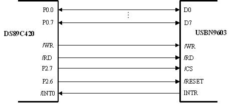
void write_usb(unsigned int usbadr, char dta);
read from USBN9603 in C like this:
char read_usb(unsigned int usbadr);
These two functions are implemented in ASM language in order for fast access.

;***************************************************************
; This subroutine is used to access USBN9603 regs , read
; USAGE: char read_usb(unsigned int usbadr);
; Argument :
; INPUT: R6&R7: address of USBN9603's reg
; OUTPUT: R7: value of that reg
;***************************************************************
_read_usb:
      PUSH DPH
      PUSH DPL
     
      MOV DPH, R6
      MOV DPL, R7
      MOVX A, @DPTR
      MOV R7,A
     
      POP DPL
      POP DPH
      RET


;***************************************************************
; This subroutine is used to access USBN9603 regs ,write
; USAGE: write_usb(unsigned int usbadr, char dta);
; Argument :
; INPUT:
; R6&R7: address of USBN9603's reg
; R5 : value to be written
; OUTPUT:
; none;
;***************************************************************
_write_usb:
      PUSH DPH
      PUSH DPL
     
      MOV DPH, R6
      MOV DPL, R7
      MOV A,R5
      MOVX @DPTR, A
     
      POP DPL
      POP DPH
      RET


DS89C420 is 8-bit microcontroller, it can't read/write to GP2021 directly, becasue GP2021 has 16-bit data bus. To solve this problem, I use DS89C420's 16 IOs to build up a 16-bit port to visit GP2021. Schematic is as below:


 GP2021 interface


Write to GP2021 in C like below:
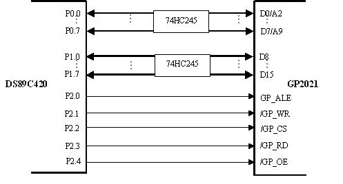
void write_gps(char add, char lo, char hi);
Read from GP2021 in C like below:
void read_gps(char add, unsigned int* datadd);
These two functions are also implemented in ASM language in order for fast access.

;************************************************************
; This subroutine is used to read one data(16bit) from gp2021
; Argument:
; INPUT: R7 --> address
; R4,R5 --> pointer for stored data
; OUTPUT:
; NONE
; USAGE :
;; read_gps(char add, unsigned int* datadd);
;************************************************************
_read_gps:
      CLR EA ; disable all int
     
      MOV DPH, R4 ; set the data pointer
      MOV DPL, R5 ;
     
      MOV P0, R7 ; send address first
     
      MOV P2,#0EFh ; GPS_OE=0, GPS_ALE = 1
      MOV P2,#0EEh ; GPS_OE=0, GPS_ALE = 0
      MOV P0,#0FFh ; setup P0 and P1
      MOV P1,#0FFh ;
      MOV P2,#0E2h ; GPS_OE=0, GPS_RD = 0, GPS_CS = 0
      NOP
      MOV A, P0 ;
      MOVX @DPTR, A ; Store the first byte
     
      MOV A, P1 ;
      INC DPTR ; data pointer ++
      MOVX @DPTR, A ; store the second one
     
      MOV P2, #0FEh ; Idle state
      SETB EA ;
      RET
;************************************************************
; This subroutine is used to write one data(16bit) to gp2021
; Argument:
; INPUT: R7 --> address
; R5,R3 --> MSB & LSB CHAR
; OUTPUT:
; NONE
; USAGE :
; write_gps(char add, char lo, char hi);
;************************************************************
_write_gps:
      CLR EA ; disable all int
      MOV P0, R7 ; send address first
      MOV P2, #0EFh ; GPS_OE=0, GPS_ALE = 1
      MOV P2, #0EEh ; GPS_OE=0, GPS_ALE = 0
      MOV P0, R3 ; Send LSB first
      MOV P1, R5 ; Send MSB next
      MOV P2, #0E8h ; GPS_OE=0, GPS_WR=0, GPS_CS=0
      MOV P2, #0FEh ; Idle state
      SETB EA ;
      RET
To provide the ISP function, I designed the schematic as below:


 serial interface


On the PCB board, PROG is connected to a jumper which is grouded. If the jumper is set, 74LS244 is enabled, then the RST=1, EA=0, PSTN=0, which invokes ROM LOADER of DS89C420 . After that user can download hex file to the board and program the code into on-chip FLASH of DS89C420 through RS232.


Welcome to USBGPS Opensource Project Homepage
© Copyright 2004    Email:   Yu Lu